Explosion-Proof Slip Ring Selection Guide for OEM Engineers: ATEX, IECEx & Hazardous Areas
2026-09-15 15:14 by admin
- Share
-

-

-

-

-

Quick Answer: How Should OEM Engineers Select an Explosion-Proof Slip Ring?
Selection of an explosion-proof slip ring should begin with the hazardous-area classification and the certification framework the project requires, then proceed through the protection concept, electrical and signal needs, mechanical duty, environmental conditions, installation interfaces, documentation, and lifecycle factors. Explosion-proof slip ring selection is both an engineering and a compliance decision, because the equipment marking and approved configuration must match the site classification. Current, voltage, and physical size alone are not sufficient selection criteria.
Key Takeaways
Confirm the hazardous-area classification before comparing slip ring options.
Identify whether ATEX, IECEx, NEC/CEC, or another acceptance framework applies.
Match electrical, signal, mechanical, thermal, and environmental requirements to the application.
Verify that the proposed protection concept and equipment marking align with the project requirements.
Review installation entries, grounding, documentation, and change control before design approval.
Use a complete RFQ to reduce specification errors and supplier clarification cycles.
1. When Does an Application Require an Explosion-Proof Slip Ring?
An explosion-protected slip ring may be required when rotating equipment must transfer power, signals, or data in a hazardous location where explosive gas, vapor, dust, or fiber may be present. The exact requirement depends on the site classification, the applicable framework, the equipment location, and the overall protection strategy. OEM engineers should treat a classified hazardous area as the trigger for a protection review rather than assuming a generic product will work.
Application Conditions to Identify First
Hazardous material type and whether it is gas, vapor, dust, or fiber.
Zone (0, 1, 2 or 20, 21, 22) or Division (1, 2).
Equipment installation location within the classified area.
Applicable regional acceptance requirements.
Whether the project is new equipment, a retrofit, or a replacement.
Why Site Classification Must Come Before Product Selection
Site classification determines the required equipment marking and protection level. In ATEX and IECEx projects the area is described by Zones; in many North American projects it is described by Class and Division. Each route points to different markings, so a slip ring must be selected against the classification at the actual installation point.
Selecting before confirming the classification creates redesign and compliance risk. The wrong gas group, temperature class, or zone rating can force a costly late redesign. Obtain the official area classification from the end user or plant owner before committing to a configuration.
2. Which Hazardous-Area Framework Applies to the Project?
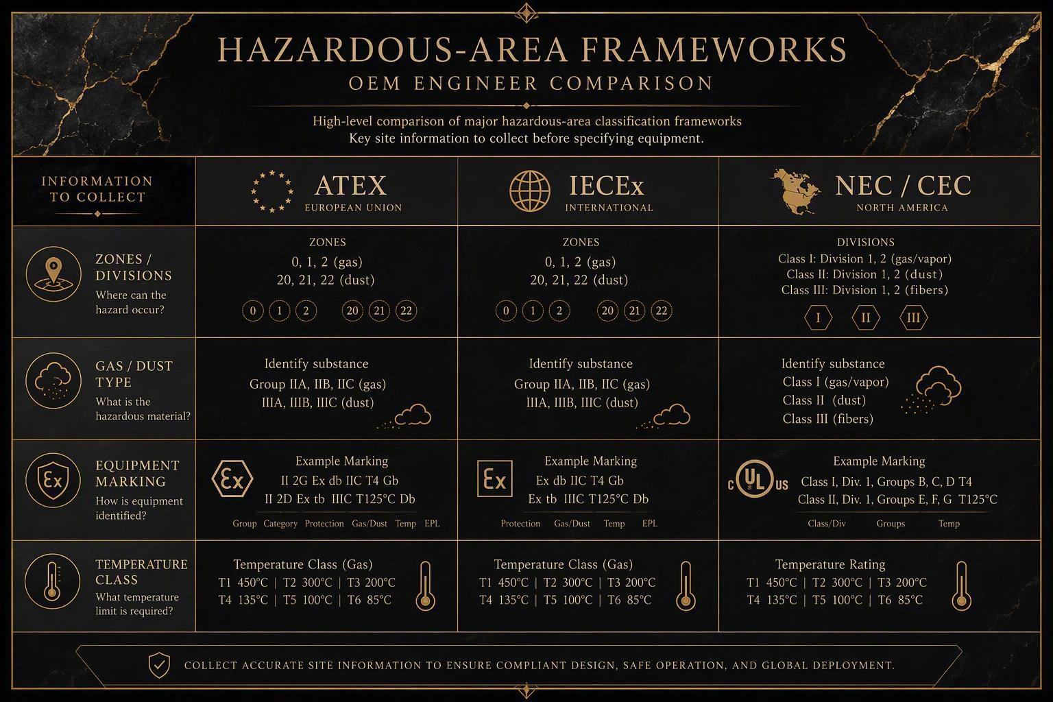
ATEX, IECEx, and NEC/CEC use different terminology and acceptance processes. OEM engineers should identify the framework required by the project's sales destination before comparing explosion-proof slip ring solutions and should not assume certificates or classifications are automatically interchangeable. The framework decision shapes the equipment marking, documentation, and approval path the design must meet.
ATEX Basics for OEM Engineers
ATEX is the European Union legal conformity framework defined by Directive 2014/34/EU. Four parts of the marking matter to OEM engineers:
Equipment groups: Group I covers mining; Group II covers surface industrial applications such as cranes and offshore equipment.
Categories: 1 (very high protection, for Zone 0/20), 2 (Zone 1/21), and 3 (Zone 2/22).
Zones: gas Zones 0, 1, and 2; dust Zones 20, 21, and 22.
Gas and dust environments and temperature classification.
Per European Commission guidance on ATEX equipment, equipment placed on the EU market for potentially explosive atmospheres must meet the directive's essential requirements. An OEM exporting to the EU should confirm the slip ring is marked for the required group, category, zone, and temperature class.
IECEx Basics for OEM Engineers
IECEx is a global, voluntary certification scheme that tests and certifies equipment to the IEC 60079 series. As the IECEx certified equipment scheme FAQ explains, an IECEx Certificate of Conformity confirms the design meets the relevant IEC standards and that the manufacturer's quality system is under surveillance. Relevant concepts for the OEM include:
Equipment Protection Levels (EPL), such as Ga, Gb, Gc for gas and Da, Db, Dc for dust.
Zones for gas and dust, gas and dust groups, and protection concepts such as Ex d, Ex p, and Ex t.
Temperature classification and maximum surface temperature.
Certificate scope: exactly what the certificate covers.
IECEx is widely recognized as a technical benchmark, but it does not automatically grant national legal approval in every country; most IECEx member countries still require some national processing for local acceptance.
NEC/CEC Class-Division and Zone Considerations
NEC (National Electrical Code, US) and CEC (Canadian Electrical Code) use a different model. Many North American installations use Class, Division, and Group, though Zone-based paths exist in NEC Articles 505/506 and Canadian equivalents. Confirm these for US and Canadian projects:
Class: I for gases and vapors, II for combustible dusts, III for fibers.
Division 1 or 2, describing how often the hazard is present.
Group, identifying the specific material.
Zone where that path is applied.
AEx or Ex markings where relevant.
NRTL listing or equivalent acceptance for US projects, and CSA or equivalent for Canada.
Do not treat ATEX, IECEx, NEC, and CEC terminology as universally equivalent. Acceptance, nameplate, and documentation differ by market. Confirm the sales destination and its framework before contacting a slip ring supplier.
3. How Should Engineers Read Hazardous-Area Equipment Markings?
Hazardous-area markings communicate the protection method, the equipment group, the gas or dust group, the temperature limitation, the equipment protection level or category, and other conditions relevant to safe use. OEM engineers should compare the required project marking with the proposed equipment documentation before approval. Reading a marking is a checklist task, because each element must match the classification, the atmosphere, and the installation conditions.
Protection Concept
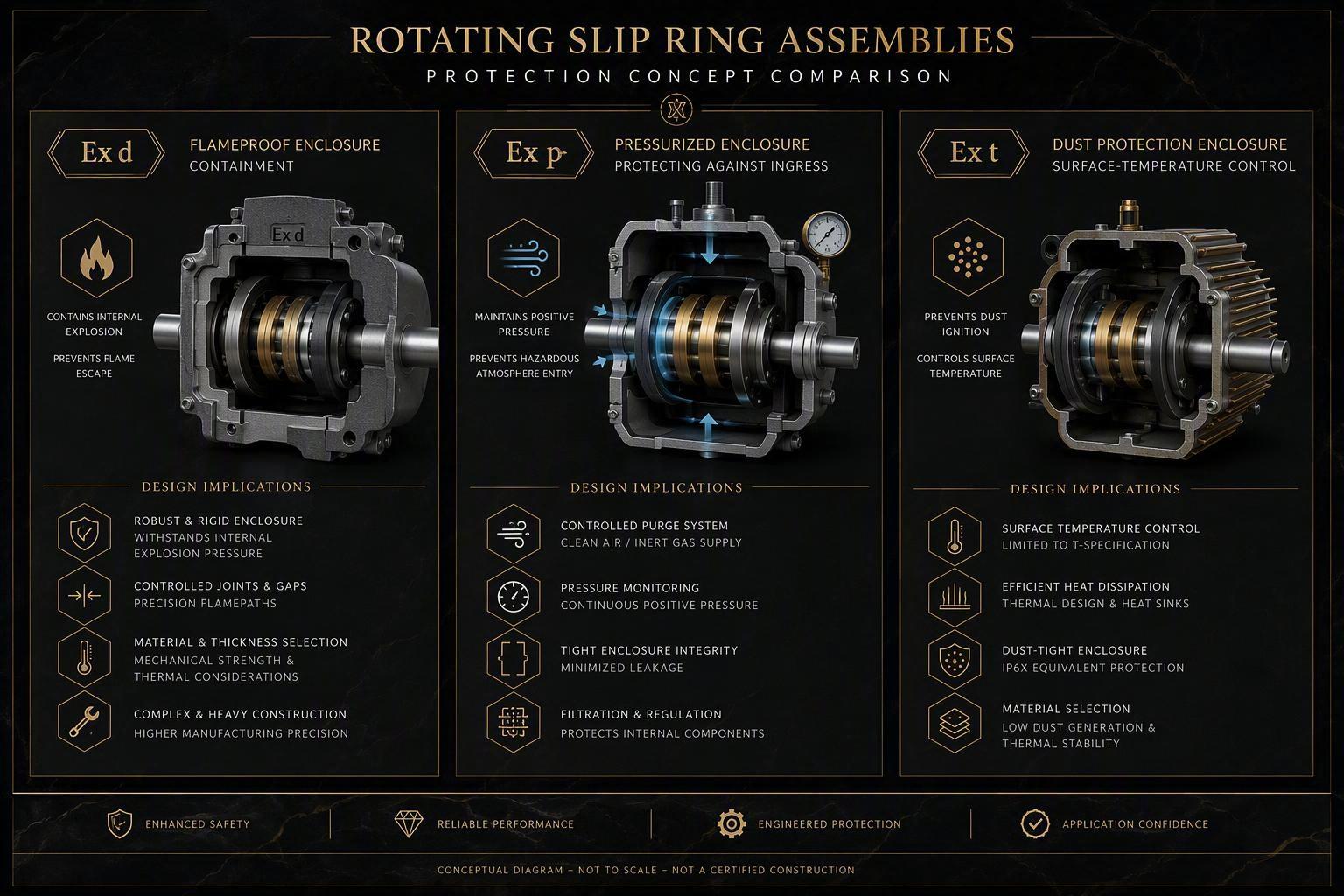
The protection concept is the core of the marking. Concepts relevant to rotating slip ring assemblies include Ex d (flameproof enclosure), Ex p (pressurized enclosure), and Ex t (enclosure protection for combustible dust). Engineers should identify which concept applies to the proposed slip ring and whether it suits the project's Zone or Division and gas or dust requirement.
Equipment Groups and Protection Levels
The group shows whether the equipment is intended for mining (Group I) or surface industry (Group II). The equipment protection level (EPL) or ATEX category indicates the protection level and the Zones it suits. During selection, filter candidates by group and protection level: a marking at a lower protection level than required is unsuitable, and exceeding the requirement should still be confirmed against the actual installation environment.
Temperature Classification and Surface Temperature
Temperature is part of selection because the equipment surface must not ignite the surrounding atmosphere. Gas equipment is often marked with a temperature class such as T1 through T6; dust equipment often states a maximum surface temperature in degrees Celsius. Confirm the slip ring's limit is below the ignition temperature of the material present with the correct margin, using the manufacturer's approved documentation.
Special Conditions and Installation Restrictions
Markings and certificates often carry special conditions, including ambient limits, approved cable entry types, installation or orientation limits, documentation conditions, and configuration limitations that define exactly which version is approved. Review these before approval. If the OEM needs something outside the approved configuration, the change should be reviewed rather than assumed to be covered.
4. Which Protection Concept Is Appropriate for a Slip Ring Assembly?
The appropriate protection concept for a slip ring depends on the complete architecture, the hazardous-area requirement, the enclosure design, the electrical load, the installation environment, and the maintenance strategy. OEM engineers should evaluate the concept as part of the whole rotating assembly rather than as an isolated product label. The correct concept emerges from how the machine is built, installed, and maintained.
Ex d and Flameproof Enclosure Considerations
Ex d containment relies on an enclosure strong enough to withstand an internal explosion and on flamepaths that prevent propagation to the surrounding atmosphere. For a rotating assembly this has specific implications:
Flamepaths and enclosure joints become part of the containment and must stay within approved limits.
Brushes and rings are enclosed so any ignition source is contained.
Enclosure integrity must hold over the equipment life.
Opening or modifying the enclosure can affect protection, so maintenance must follow the approved procedure.
Flameproof construction is a well-established approach for gas atmospheres. However, "flameproof" or "explosion-proof" labels are not identical to every other protection concept, and a flameproof slip ring does not automatically satisfy every project's certification route.
Ex p Pressurization for Complex Assemblies
Pressurization (Ex p) keeps the hazardous atmosphere out by maintaining positive internal pressure with a protective gas. It may be considered when a complex assembly cannot be cost-effectively contained as a flameproof enclosure or when the whole system already uses pressurization.
Ex p carries system-level implications: it needs a source of pressurized protective gas and associated control, pressure and purge monitoring so equipment runs only under safe conditions, and maintenance that keeps the pressurization system functional. An OEM considering Ex p should treat the slip ring as part of a larger pressurized system, not an isolated component.
Ex t for Combustible-Dust Applications
Ex t focuses on preventing dust ingress and controlling surface temperature so settled or airborne dust cannot ignite. Consider the enclosure sealing and joints, the maximum external surface temperature relative to the dust, and whether the unit sits in a dust cloud or dust layer setting. An OEM selecting for a dust atmosphere should confirm the marking addresses dust, because a gas-only marking is not automatically suitable for dust duty.
When Multiple Requirements Must Be Considered Together
Real projects often combine gas, dust, and wet conditions, and integrated assemblies may use more than one protection concept across components. Engineers should evaluate the gas-versus-dust environment, integrated assemblies, regional acceptance requirements, and the complete-system configuration together before settling on a slip ring design.
5. What Electrical and Signal Requirements Must Be Defined?
Hazardous-area compliance does not determine whether a slip ring will meet the machine's electrical and communication needs. OEM engineers should separately define power circuits, current, voltage, signal types, data protocols, shielding, grounding, and mixed power-and-signal requirements. Compliance approves the enclosure; the electrical specification defines whether the slip ring actually carries the right power and signals.
Power Requirements
A supplier needs more than total current, voltage, and wire count. Define each circuit: current per circuit rather than only a total, operating voltage, AC or DC, continuous versus intermittent loading, peak or inrush conditions where relevant, and duty cycle. Omitting the load profile can size circuits for the wrong condition; an intermittent high-inrush motor circuit and a continuously loaded heater place very different demands on the same wire count.
Signal and Data Requirements
Define the signal and communication channels: analog signals, digital signals, encoder signals, CAN, Industrial Ethernet, and any other application-specific needs. Mixed power and data raise noise and crosstalk concerns, and the design must manage separation of sensitive channels from power channels. Because actual performance depends on the complete configuration, do not assume a generic throughput figure; let the supplier evaluate the channel layout.
Shielding, Grounding, and Circuit Separation
Clarify power-to-signal separation within the slip ring, shielding for sensitive or data channels, the grounding strategy for the rotating interface, the noise sensitivity of connected instrumentation, and signal-integrity expectations. Clear requirements let a supplier recommend the right channel arrangement. A slip ring that is electrically correct but communicatively noisy will still fail in service.
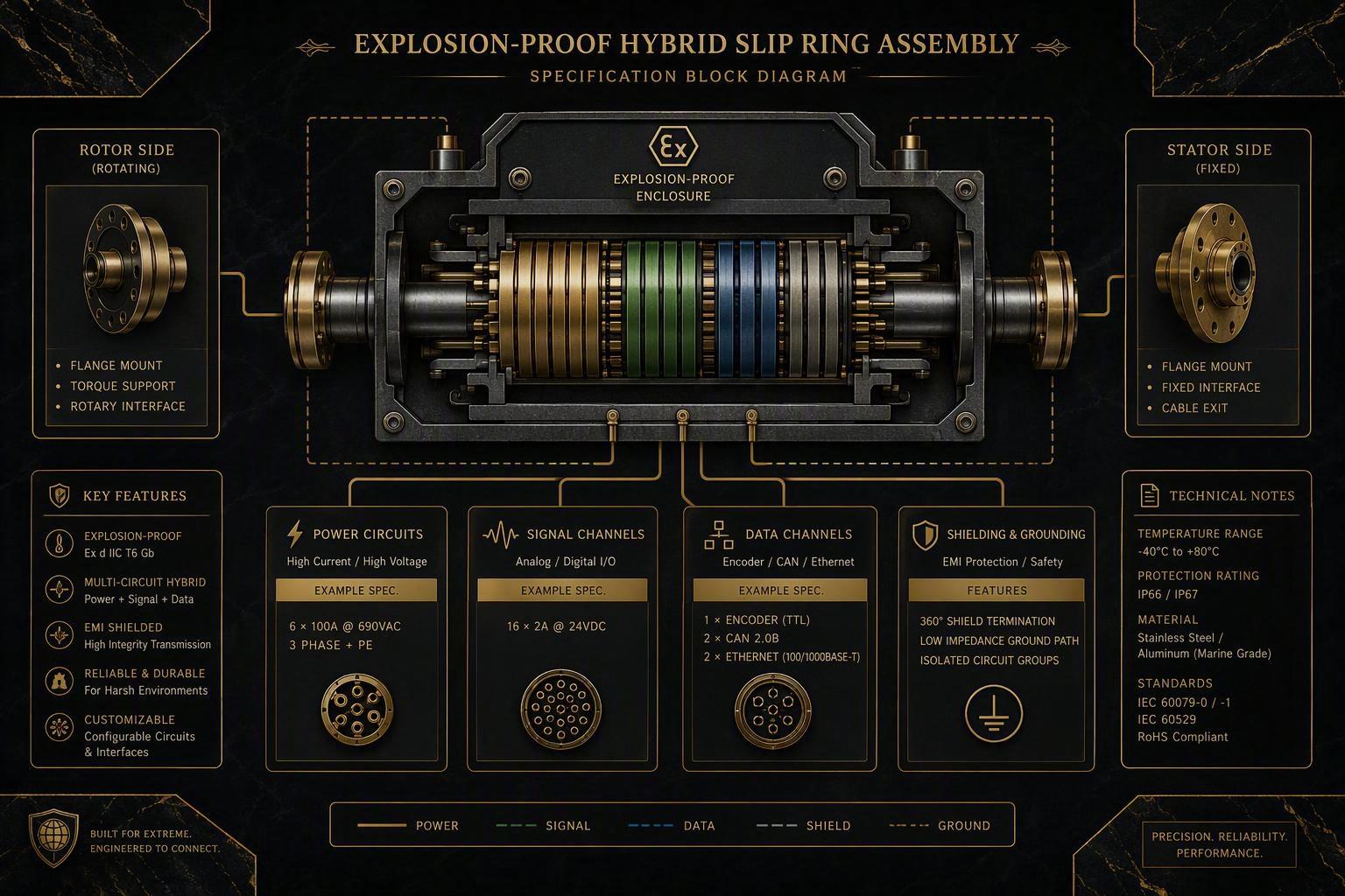
6. What Mechanical and Environmental Conditions Affect Slip Ring Selection?
Rotational duty, mounting, space limitations, bearings, cable routing, vibration, temperature, moisture, dust, and corrosive conditions can all affect the mechanical architecture and suitability of an explosion-proof slip ring. OEM engineers should give realistic operating conditions rather than idealized ones. A slip ring chosen on nominal ratings alone can fail when real vibration, temperature, or duty is applied.
Rotational Duty
Define operating speed; whether rotation is continuous or intermittent; start-stop frequency; duty cycle; and mechanical loading on the rotating interface. A continuously rotating high-speed machine and a slowly oscillating slewing drive demand different bearing and wear behavior, and frequent start-stop can change thermal and wear expectations.
Mechanical Interface
Supply shaft or through-bore requirements, mounting method, the available installation envelope and maximum dimensions, cable exit direction, bearing arrangement, and service access. In tight slewing sections, space is often the binding constraint, and cable exit direction determines how a rotating assembly routes cables without binding.
Environmental Conditions
State ambient temperature range, dust levels, moisture and washdown exposure, outdoor exposure, corrosive atmosphere, vibration and shock, and other application-specific conditions. Ingress protection and corrosion resistance are separate from hazardous-area protection, and both must be specified for the slip ring to survive its physical surroundings.
7. How Should Electrical Load and Thermal Conditions Be Evaluated?
Electrical loading, enclosure design, ambient conditions, simultaneous circuit loading, and operating duty together influence heat generation and thermal performance. OEM engineers should define actual operating conditions rather than relying only on nominal ratings, because heat builds from how the slip ring is really used. A configuration that is comfortable at light load can run hot when all circuits carry current near their limit in a warm enclosure.
Sources of Internal Heat
Heat comes from electrical loading across the contacts, contact resistance at the brush-and-ring interface, simultaneous circuit operation, and the enclosure's ability to dissipate heat. Simultaneous loading matters: if every circuit carries near-rated current at once, internal heat is higher than the per-circuit rating implies. Describe the real load profile so the supplier can assess the temperature rise.
External Thermal Conditions
The environment also affects heat removal: ambient temperature, nearby heat sources such as a motor or process, restricted airflow, and installation inside an enclosed, poorly ventilated space. A slip ring in a warm, enclosed location must shed heat differently from one in open, cooler air. Report the realistic ambient and installation enclosure.
Thermal Review Before Final Selection
Set the operating conditions for the review, consider derating where real ambient or simultaneous loading exceeds a benign assumption, review temperature rise rather than assuming a nominal figure, and for hazardous-area equipment confirm surface-temperature limits for the approved atmosphere. Because approval can restrict surface temperature, the thermal review connects directly to compliance. Exact derating or temperature values come from the supplier's documentation for the specific configuration, not from a general rule.
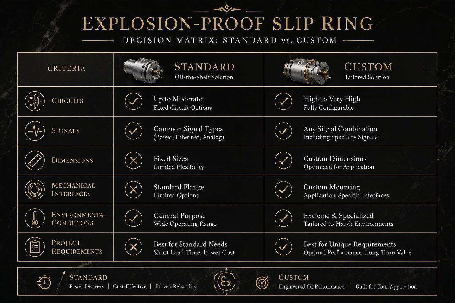
8. Standard or Custom Explosion-Proof Slip Ring: Which Approach Fits the Project?
A standard solution is preferable when the electrical, mechanical, environmental, and compliance requirements already match an existing configuration. Customization may be appropriate for special circuits, signals, interfaces, dimensions, or integration features, but design changes should be reviewed for their impact on the approved configuration. The decision is about which option verifiably meets the requirements with the least added risk, not which sounds more capable.
When a Standard Configuration May Be Preferred
Choose a standard configuration when existing dimensions fit the machine and envelope, circuit requirements are compatible, required electrical and signal interfaces are available, environmental conditions are within the intended application range, and the available documentation meets compliance needs. A standard unit typically lowers integration complexity and eases specification when the interfaces already fit; there is no reason to add custom risk when a proven configuration matches.
When Customization May Be Required
Customize when a real requirement cannot be met by a standard product: special circuit combinations, mixed power and signal transmission with a specific channel layout, restricted installation space, special mechanical interfaces or mounting and bore/shaft arrangements, custom cable or connector arrangements, or application-specific integration. Request customization only when a standard product genuinely cannot meet the requirement.
How Customization Can Affect Compliance
Customization is not compliance-neutral. Enclosure, flamepath, cable-entry, electrical-load, material, and mechanical-interface changes can all affect an approved protected configuration and may need review before final approval. One certified product does not automatically mean every customized variant carries the same certification status. Ask the supplier to confirm whether a customized design stays within the approved configuration or requires a new evaluation.
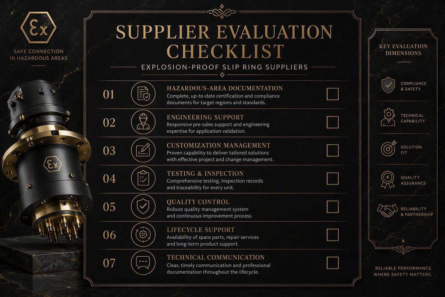
9. What Should OEMs Evaluate When Comparing Explosion-Proof Slip Ring Suppliers?
Supplier evaluation should go beyond electrical ratings and price. OEM engineers and technical procurement teams should review hazardous-area documentation, engineering support, customization control, testing and inspection processes, documentation quality, lifecycle support, and the supplier's ability to understand the complete application. A low-priced supplier with thin hazardous-area documentation can create more risk than a higher-priced one that proves the configuration is correct.
Documentation and Compliance Support
Ask the supplier to supply and keep current: equipment markings and associated certification documentation, certificates where applicable to the project framework, drawings of the proposed configuration, installation documentation, configuration records that define exactly what is approved, and change-control documentation. For hazardous-area equipment, documentation is the evidence that the configuration matches the required marking. If the supplier cannot clearly state the marking and its coverage, treat that as a red flag.
Engineering Support
The supplier should review the application rather than just sell a part: application requirements, electrical configuration, signal integration, mechanical integration, design review, and customization coordination. Good engineering support catches conflicts between the compliance requirement and the electrical or mechanical design before the machine is built.
Testing and Quality Control
Evaluate how the supplier confirms quality and whether testing is documented: electrical inspection, mechanical inspection, application-specific validation where required, and documentation and traceability. Test values and standards depend on the configuration and framework, so request the inspection and test documentation for the actual unit rather than accepting an unsupported general testing claim.
Lifecycle Support
Consider maintenance guidance, replacement planning, spare parts, technical communication, and project schedule and delivery discussion. Lifecycle support matters because approved configurations must be preserved in the field; a supplier that documents the unit and controls change makes it easier to keep the installation compliant over time.
10. What Should Be Verified Before the OEM Freezes the Machine Design?
The proposed explosion-proof slip ring should be reviewed against the hazardous-area specification, electrical requirements, signal requirements, mechanical interfaces, environmental conditions, installation details, and documentation requirements before the machine design is finalized. Each review area must hold under real operating conditions, because a design freeze locks in assumptions that are expensive to change later.
Hazardous-Area Review
Confirm that the slip ring's site classification, required equipment marking, applicable acceptance framework, protection concept, and installation conditions are all matched. The marking and certificate must cover the actual classification, not a similar-looking one.
Electrical Review
Verify the circuit count, current, voltage, signal types, communication protocols, and shielding and grounding are complete and consistent, and that the layout supports both power and data needs.
Mechanical Review
Confirm the dimensions, mounting, shaft or bore interface, rotation, cable routing, and service access. A slip ring that fits on paper but cannot be installed or maintained will fail in practice.
Environmental Review
Match the design to the real temperature, dust and moisture, corrosion, vibration, and outdoor or industrial exposure.
Documentation Review
Before freeze, confirm the drawings, product documentation, installation requirements, change-control requirements, and inspection or project records are complete. Incomplete documentation locks in a configuration the compliance record may not yet support.
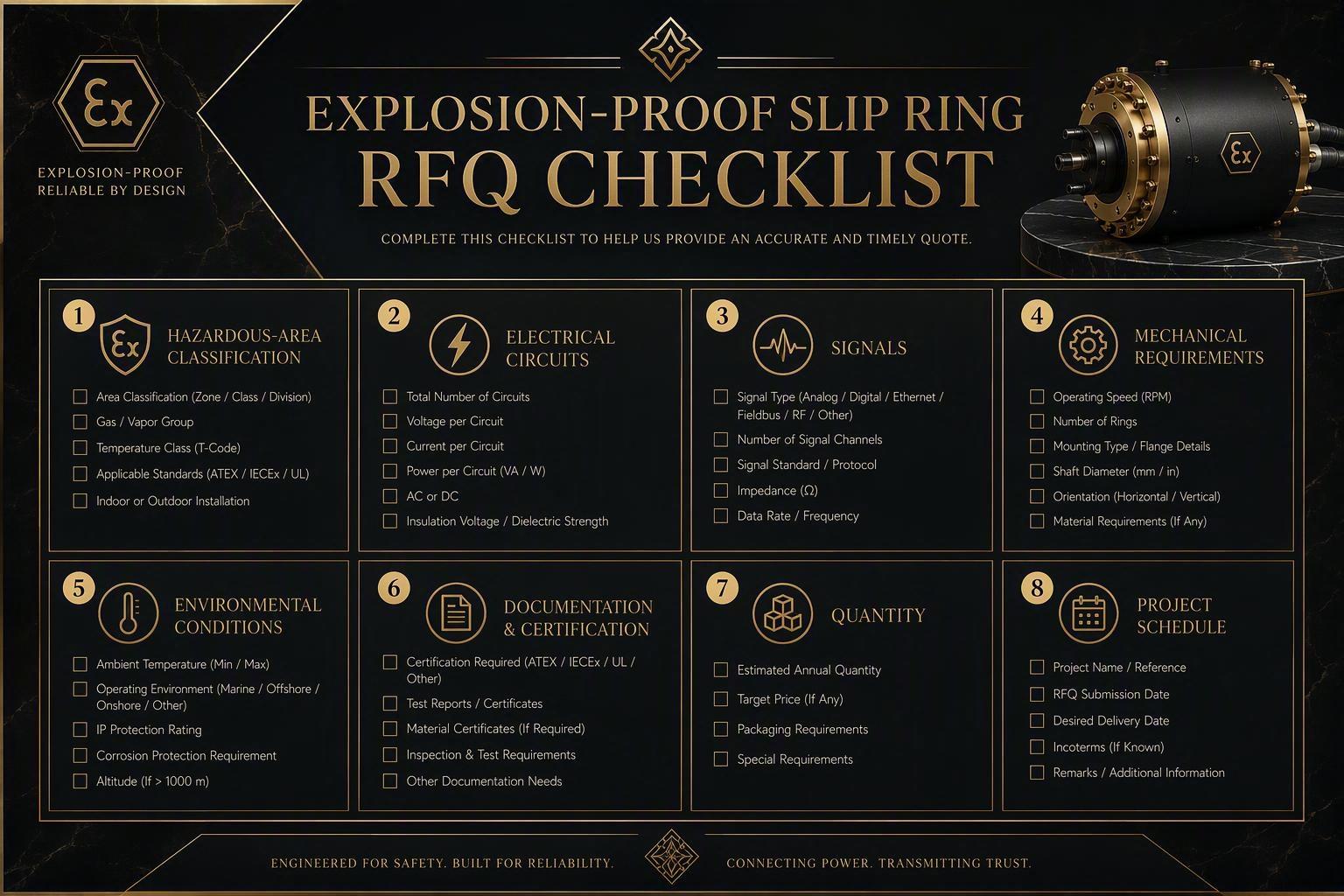
11. What Information Should Be Included in an Explosion-Proof Slip Ring RFQ?
A complete explosion-proof slip ring RFQ should combine hazardous-area information with electrical, signal, mechanical, environmental, and project requirements. A detailed RFQ lets the supplier evaluate the complete rotating-interface application rather than recommending a product from only a keyword or basic electrical rating. The more complete the RFQ, the fewer clarification cycles and the lower the chance of an unsuitable configuration.
Hazardous-Area Information
Start with the compliance picture: installation country or market; applicable framework (ATEX, IECEx, NEC/CEC, or other); Zone or Division; gas or dust environment; required equipment marking; and customer or project compliance requirements. Missing hazardous-area data is the most likely cause of delay, because a supplier cannot recommend an approved configuration without it.
Electrical Information
Supply the circuit count, current requirements, voltage, AC or DC, load profile including continuous and peak conditions, and signal and data requirements.
Mechanical Information
Define maximum dimensions, mounting interface, shaft or through-bore requirement, rotational speed, duty cycle, and cable routing.
Environmental Information
State the temperature, dust, water or moisture, corrosion, vibration, and outdoor or marine exposure where relevant.
Project and Commercial Information
Close out with whether this is a prototype or production project, estimated quantity, project schedule, documentation requirements, inspection requirements, and requested quotation scope. Completing these categories reduces specification errors and lets the supplier move from a general discussion to an actual configuration.
12. What Are the Most Common Explosion-Proof Slip Ring Selection Mistakes?
Common mistakes occur when the hazardous-area requirement is separated from the electrical and mechanical design of the machine. OEM engineers should avoid selecting by ratings alone, assuming certification frameworks are interchangeable, ignoring temperature and thermal conditions, ignoring installation details such as cable entries and grounding, changing critical design elements after the protection strategy is set, failing to review the complete marking, and waiting until final design to address hazardous-area requirements.
Selecting by Current and Voltage Alone
The mistake is choosing a slip ring only by current and voltage. A unit that carries the right current can still be unsuitable if its marking, mechanical fit, or thermal behavior does not match. Instead, evaluate the full requirement set: marking, electrical profile, mechanical interface, environment, and duty.
Treating Different Hazardous-Area Frameworks as Automatically Equivalent
The mistake is assuming ATEX, IECEx, or NEC/CEC solutions are interchangeable across markets, when their acceptance processes differ. Instead, identify the framework for the actual sales destination and confirm the equipment and documentation meet it.
Ignoring Temperature and Thermal Conditions
The mistake is ignoring how heat builds under real simultaneous load and ambient temperature, which can push surface temperature beyond what the atmosphere allows. Instead, provide the realistic load profile and ambient conditions for a thermal and surface-temperature review.
Ignoring Cable Entries, Threads, Bonding, and Grounding
The mistake is focusing on the slip ring body while ignoring how it is connected and grounded. Incorrect entries, threads, seals, bonding, or grounding can compromise the installation. Instead, specify and review entries, sealing, and grounding as part of the configuration.
Changing Enclosure or Interface Details Late in the Design
The mistake is modifying the enclosure or mechanical interface after the protection strategy is fixed, which can void the intended approval. Instead, raise changes before the design freeze and confirm whether the approved configuration is preserved.
Failing to Review the Complete Equipment Marking and Documentation
The mistake is checking only part of a marking or accepting a broad claim without the certificate. A marking contains several elements that must all match. Instead, read the complete marking and review the certificate, drawings, and documented configuration before approval.
Waiting Until Final Machine Design to Address Hazardous-Area Requirements
The mistake is treating hazardous-area selection as a last step. Deferring the review can force a redesign and add documentation and integration delays. Instead, bring the hazardous-area requirement and the slip ring decision in early, before the machine layout and circuits are fixed.
13. How Should Installation and Maintenance Preserve the Approved Configuration?
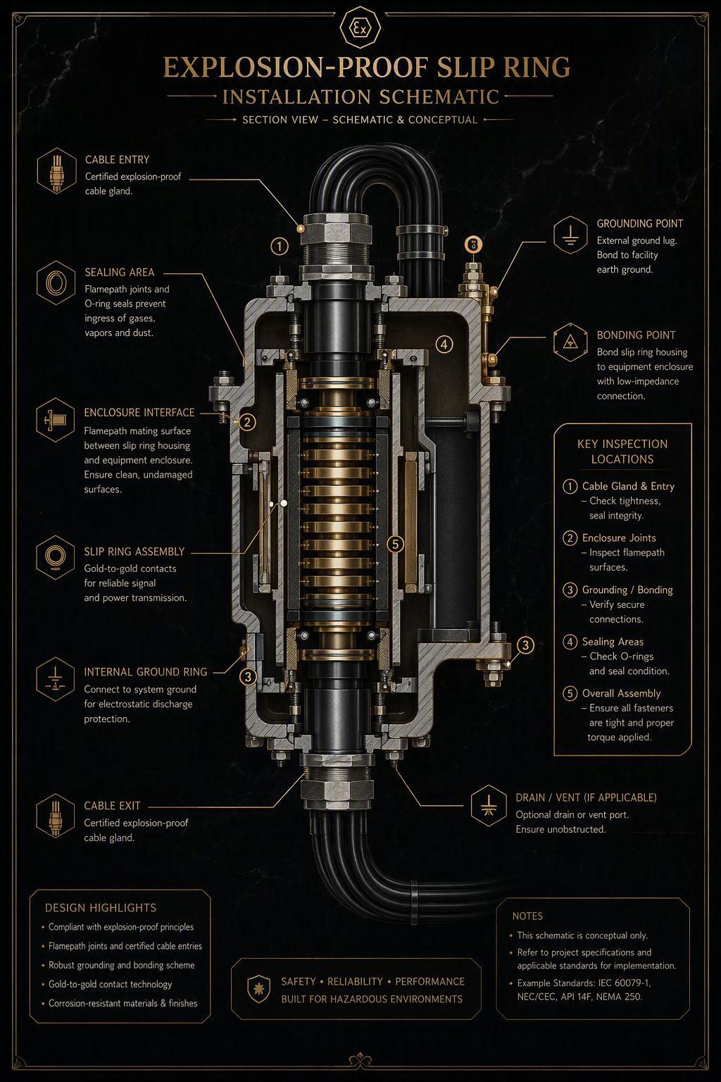
Product selection alone is not sufficient. Installation entries, bonding, grounding, enclosure integrity, inspection, maintenance, replacement parts, and later modifications should be controlled so the intended protection strategy is not unintentionally compromised during the equipment lifecycle. An approved slip ring stays compliant only if those who install and service it preserve the exact approved configuration.
Cable Glands, Entries, and Thread Interfaces
Cable and conduit connections are part of the protected assembly. Use correct certified cable glands and entries for the atmosphere, confirm thread compatibility, and follow the manufacturer's installation documentation so entries do not weaken the enclosure.
Bonding and Grounding
Confirm protective bonding is continuous, use the designated grounding interfaces, and consider system-level grounding requirements. A proper ground path is part of the safety principle, not an option.
Inspection and Maintenance
Follow the manufacturer's inspection and maintenance instructions, inspect enclosure and connection integrity, inspect wear-related components such as brushes and rings, and keep records. This preserves the approved configuration over the equipment life.
Replacement and Modification Control
Review replacement components against the approved configuration, avoid uncontrolled field changes, review mechanical and electrical modifications before making them, and maintain configuration records so the installed unit stays traceable. For hazardous-area equipment, an uncontrolled field change can silently remove the protection the design was built to provide.
14. How Can JINPAT Support the Selection Process?
At the point where the OEM has defined the application requirements and needs an engineering review, product recommendation, or a discussion of a customized configuration, a slip ring specialist can help translate those requirements into a practical proposal. JINPAT focuses on engineered rotary transmission solutions and custom integration for demanding industrial machines. This is where a manufacturer's engineering input adds value rather than begins promotion.
Application Requirement Review
Share the hazardous-area, electrical, signal, mechanical, and environmental requirements for engineering discussion. The review matches the slip ring configuration to the application and checks that the proposed approach fits the duty and integration constraints.
Customization Discussion
OEM projects often need application-specific electrical or mechanical configurations. Discussing these early, before the machine design is finalized, lets engineering evaluate options such as circuit layout, channel separation, mechanical interfaces, and integration. Because a change can affect a protected configuration, the engineering discussion should stay accurate about compliance impact.
Next-Step Options
When the application requirements are defined, qualified OEM readers can proceed by:
Contacting JINPAT for an application review.
Discussing slip ring requirements with a JINPAT engineer.
Submitting application requirements for a product recommendation.
Requesting a quotation based on the project's operating conditions.
15. Explosion-Proof Slip Ring Selection Checklist
Before approving a slip ring or submitting an RFQ, OEM engineers should confirm the minimum information below. A configuration should not move forward until the hazardous-area, electrical, signal, mechanical, environmental, supplier, and documentation items are all defined and consistent.
Hazardous-Area Checklist
Installation market identified
Applicable framework identified
Zone or Division identified
Gas or dust environment identified
Required equipment marking identified
Installation requirements identified
Electrical and Signal Checklist
Circuit quantity defined
Current requirements defined
Voltage defined
Signal and communication requirements defined
Shielding and grounding requirements defined
Mechanical and Environmental Checklist
Installation dimensions defined
Mounting interface defined
Rotational requirements defined
Duty cycle defined
Environmental conditions defined
Supplier and Documentation Checklist
Proposed configuration reviewed
Drawings reviewed
Installation requirements reviewed
Documentation requirements agreed
Customization changes reviewed
RFQ information completed
16. Frequently Asked Questions About Explosion-Proof Slip Rings
What Is an Explosion-Proof Slip Ring?
An explosion-proof slip ring is a rotary electrical connector that transfers power, signals, or data across a rotating interface using an approved enclosure and protection concept so it does not ignite an explosive atmosphere. It is selected against the hazardous-area classification, equipment marking, and certification framework of the installation. Selection should combine the compliance requirement with the machine's electrical and mechanical needs.
What Is the Difference Between Explosion Protection and an IP Rating?
Hazardous-area protection and ingress protection (IP) address different risks. Explosion protection manages the risk of igniting an explosive atmosphere, while an IP rating describes resistance to solid and liquid ingress such as dust and water. An IP rating does not make a product explosion-protected, and a hazardous-area rating does not by itself guarantee water or dust resistance.
What Is the Difference Between ATEX and IECEx for Slip Ring Selection?
ATEX is the European Union legal conformity framework, while IECEx is a global certification scheme based on IEC 60079 standards. For a slip ring sold and installed in the EU, ATEX requirements apply; for global markets, IECEx is often requested as a technical benchmark. The two are not automatically interchangeable, and neither automatically equals US or Canadian acceptance under NEC or CEC.
Can an Explosion-Proof Slip Ring Transmit Both Power and Signals?
Yes. An explosion-proof slip ring can carry power, signals, and data together, but the mixed transmission must be defined and evaluated as part of the complete configuration. Sensitive and power channels need controlled separation, shielding, and grounding to preserve signal integrity. Specify the full circuit and data list so the supplier can assess the channel arrangement.
When Should an OEM Choose a Customized Slip Ring?
Choose a customized slip ring when a standard configuration does not match the machine's electrical, signal, mechanical, or integration requirements. Customization may suit special circuit combinations, restricted space, specific mechanical interfaces, or custom cabling. Because customization can affect an approved protected configuration, review the change before the design is finalized.
What Information Should Be Sent to a Slip Ring Supplier?
Send the hazardous-area classification and framework, required equipment marking, electrical circuit details, signal and data requirements, mechanical dimensions and mounting, environmental conditions, and project information such as quantity and schedule. Missing environmental or mechanical detail often delays engineering review or leads to an unsuitable recommendation.
Should Hazardous-Area Requirements Be Reviewed Before Machine Design Freeze?
Yes. Hazardous-area requirements should be reviewed before the machine design is frozen, because early review reduces the redesign, documentation, and integration problems that appear when a protection requirement is added too late. Confirm the marking, protection concept, and approved configuration before costly design changes are locked in.
Conclusion: From Hazardous-Area Requirements to a Complete Slip Ring RFQ
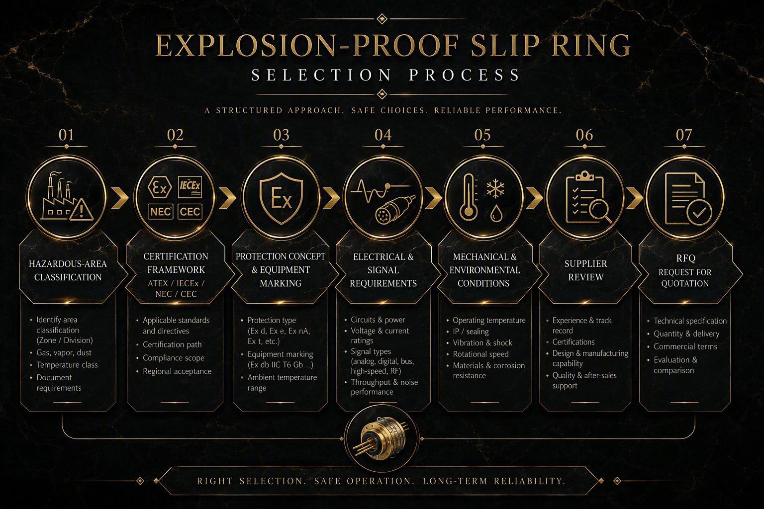
Selecting an explosion-proof slip ring should follow a defined sequence: confirm the hazardous-area requirement, identify the applicable framework, define the electrical and signal needs, define the mechanical and environmental conditions, review the protection concept and installation details, evaluate the supplier, and prepare a complete RFQ. Explosion-proof slip ring selection combines compliance, engineering, integration, and lifecycle considerations, so no element should be decided in isolation. OEM engineers should be confident about the classification, marking, and configuration before contacting a supplier.
For an application review: Contact JINPAT to discuss your hazardous-area, electrical, signal, mechanical, and environmental requirements with an engineer and explore a suitable explosion-proof slip ring configuration for your machine.