Slip Ring Specification Checklist for OEM Engineers: What to Send Before RFQ
2026-09-10 17:09 by admin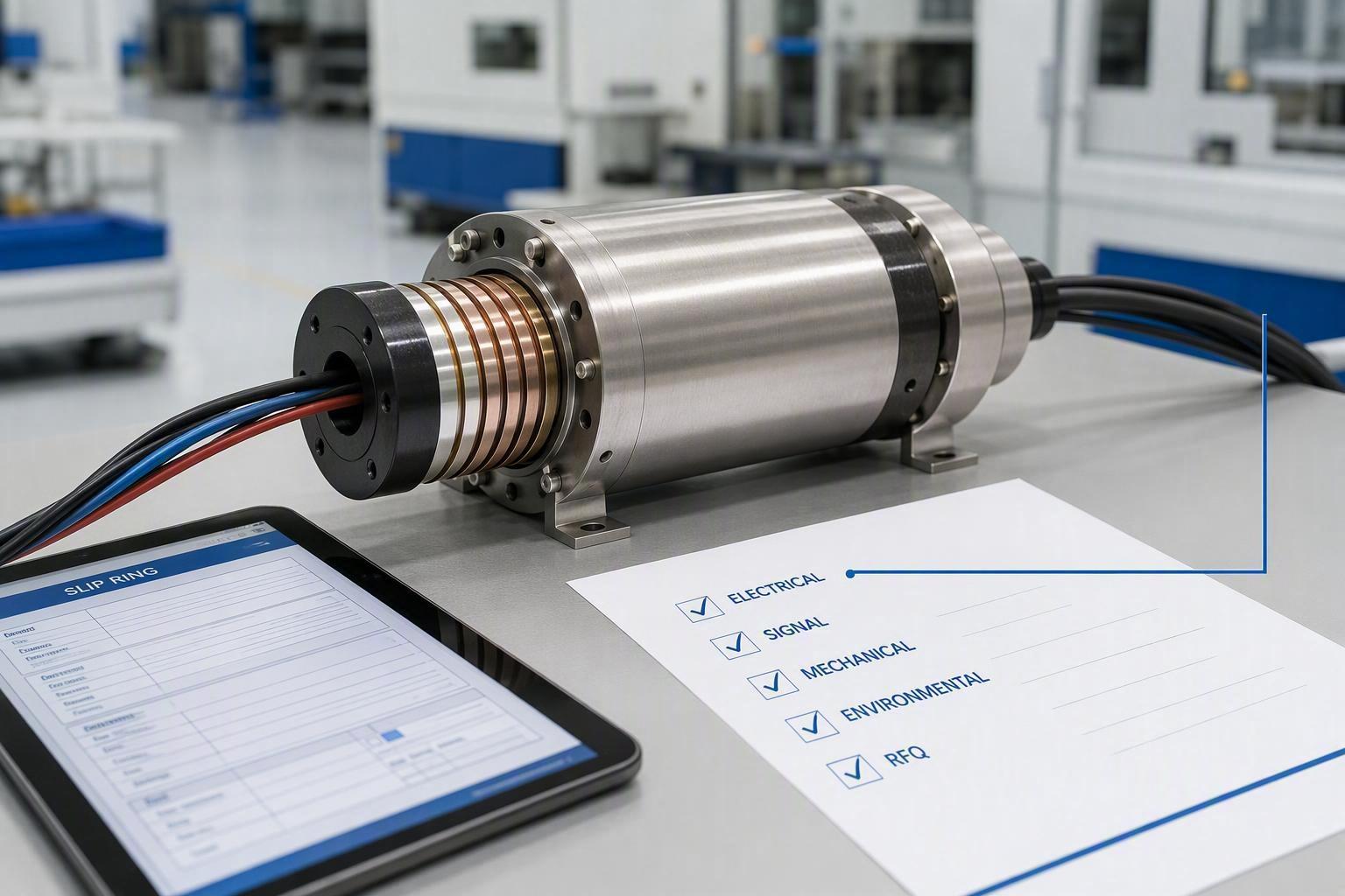
- Share
-

-

-

-

-

Quick Answer: What Information Should You Provide Before Ordering a Slip Ring?
A complete slip ring specification should define the machine application, the electrical circuits, the signals and data, the rotational profile, the mechanical envelope and mounting, the operating environment and protection needs, the cable and connector interfaces, the expected validation, the target quantity, and the project schedule. Complete application data lets a supplier recommend a suitable standard configuration or evaluate a custom design.
A slip ring should not be specified only by circuit count, current, or outside diameter. Those figures rarely carry enough context for an engineer to judge real speed, heat, fit, and environmental demand. The goal is a specification package that supports engineering review and an accurate RFQ rather than a list the supplier must guess at.
Key Takeaways
Define the machine application before you list electrical parameters.
Specify current and voltage by circuit rather than only giving totals.
Identify signal protocols and performance requirements clearly.
Provide rotational speed, duty cycle, and the full motion profile.
Include mechanical drawings, installation space, mounting method, and cable routing.
Describe the actual operating environment rather than relying only on a generic IP requirement.
State any required testing, documentation, or compliance requirements.
Include quantity, project stage, and schedule in the RFQ package.
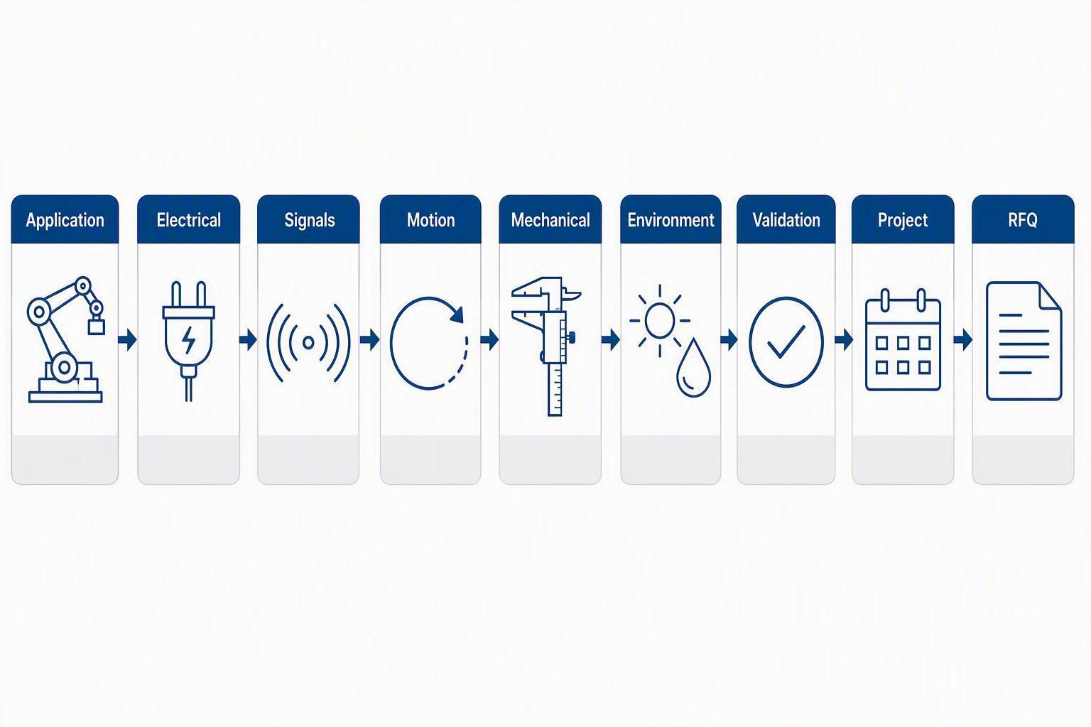
1. What Application Information Should You Define First?
The supplier needs to understand what the slip ring does inside the machine before evaluating individual specifications. Application context — the equipment type, the rotating function, the motion profile, and the reliability expectation — determines which electrical, mechanical, environmental, and validation requirements are relevant, and it stops the specification from becoming a disconnected list of parameters that are hard to interpret on their own.
Machine Function and Application Context
Describe the machine and the role the rotating interface plays.
Type of equipment: crane, excavator, drilling rig, robot, rotary table, or other machine.
Function performed by the rotating interface: what must pass from the fixed side to the rotating side.
New design, retrofit, or replacement project.
Prototype, pilot, or full-production application.
Critical operating conditions, such as continuous heavy load.
Space or integration constraints.
This context is not filler. A supplier who knows the machine can weigh trade-offs — for example, whether a tight bore or a shared high-current and signal set matters more — instead of treating each number independently.
Rotation Type, Speed, and Duty Cycle
Explain how the interface actually rotates.
Continuous or intermittent rotation; oscillating or full 360-degree motion.
Required operating speed, plus typical versus maximum speed.
Start-stop frequency and operating hours or cycles where relevant.
Expected duty cycle.
A single maximum RPM rarely captures real demand. A unit slowly rotating for 20 hours a day places a different load on contacts and bearings than a brief high-speed index once an hour. Record both the normal case and the worst case.
Reliability and Service Expectations
State how the machine is maintained and the role of uptime.
Expected maintenance approach and service access after installation.
Replacement strategy for a machine that stays in service for years.
How critical the slip ring is to overall reliability.
Required operating-life target when the project defines one in hours or revolutions.
2. What Electrical Power Requirements Must Be Included in a Slip Ring Specification?
Electrical requirements should be specified by individual circuit whenever possible. OEM engineers should provide circuit quantity, operating voltage, continuous current, peak or inrush conditions, AC or DC characteristics, grounding, isolation needs, and load behavior so the supplier can evaluate conductor sizing, contact design, thermal performance, and circuit arrangement.
Circuit Count, Voltage, and Current
List each circuit instead of giving only a total.
Number of power circuits.
Voltage for each circuit or circuit group.
Continuous current for each circuit.
Peak or temporary current where relevant.
AC or DC operation.
Different power levels in the same slip ring, such as a high-current motor feeder beside low-current control circuits.
"400 A total" is far less useful than "one 300 A motor circuit plus six 10 A control circuits at 24 V DC." That split drives real choices about ring sizing and circuit isolation.
Inrush, Peak Loads, and Duty Conditions
Continuous current alone does not describe demand.
Motor starting current and how long it lasts.
Capacitive or inductive loads where relevant.
Intermittent high-current loads and simultaneous circuit loading.
Load duration and repetition so the duty cycle is clear.
Isolation, Grounding, and Safety Requirements
Capture electrical handling and protection.
Protective ground circuits.
Circuit isolation requirements between power and control.
Power-to-signal separation.
Customer-defined insulation or safety requirements and any acceptance criteria.
3. What Signal and Data Information Should You Send to the Supplier?
Naming a signal as only "data" or "Ethernet" is usually not enough. Engineers should identify the protocol, channel quantity, required performance, shielding, grounding, impedance or signal-integrity needs, connector interface, and coexistence with power circuits so the rotating transmission method can be evaluated correctly.
Signal Type and Channel Requirements
State which transmission method each channel uses.
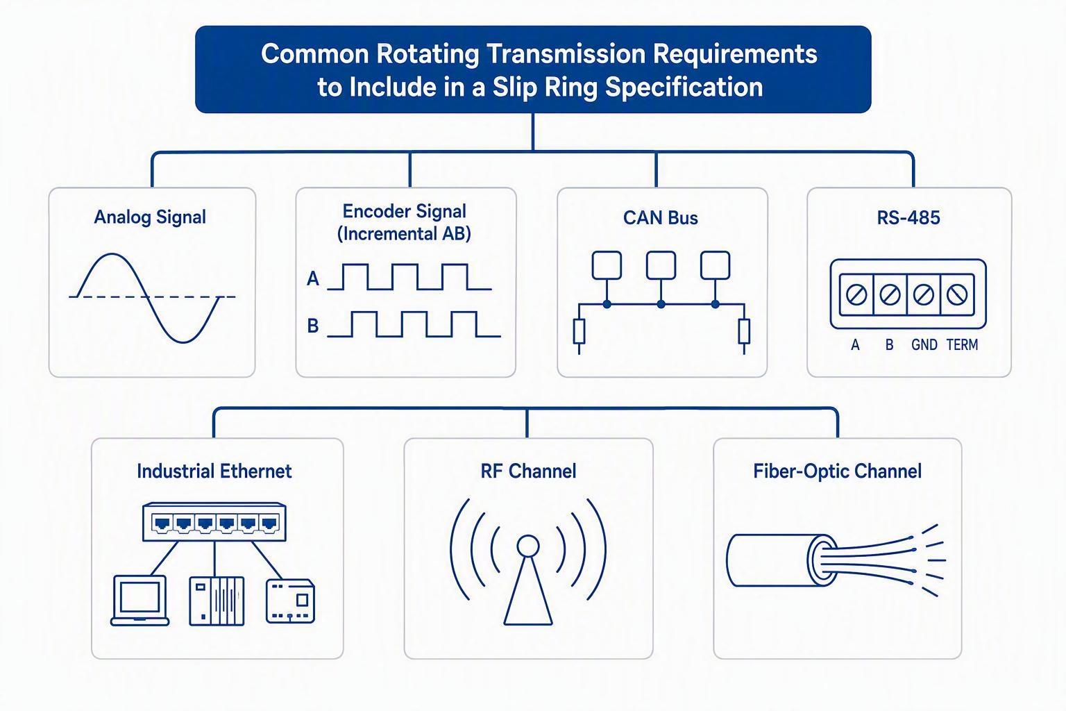
Analog signals, such as 4–20 mA control loops.
Digital signals, including discrete or high-speed channels.
Encoder signals, noting incremental or absolute type.
CAN, RS-485, or another serial fieldbus.
Industrial Ethernet or other machine-specific interfaces.
A low-frequency encoder pulse and a high-rate Industrial Ethernet link impose very different demands, so a phrase like "sends data" cannot support sound sizing.
Communication Performance Requirements
Go beyond the protocol name when performance matters.
Protocol and version or profile.
Number of channels.
Required data rate or network standard where relevant.
Signal integrity, plus latency or synchronization needs when critical.
Required shielding.
Shielding, Crosstalk, and Circuit Separation
Sensitive signals often run beside power, so define protection.
Shielded versus unshielded circuits and the grounding strategy.
Power-to-signal separation within the rotating interface.
Noise-sensitive channels that should not share proximity with high-current rings.
Connector and cable requirements, including type and orientation.
When RF Rotary Joints or Fiber Optic Rotary Joints May Be Considered
Some needs cannot be met with conductive signal rings alone.
High-frequency RF transmission, such as antennas or radar across rotation.
Fiber-optic communication for high isolation or very high bandwidth.
Electrical isolation that a conductive path cannot provide.
Integrated architectures combining power and signal or data in one rotary union.
Describe such needs clearly so the review can confirm which transmission method fits, rather than assuming a generic data path will work.
4. What Mechanical Dimensions and Installation Details Are Required?
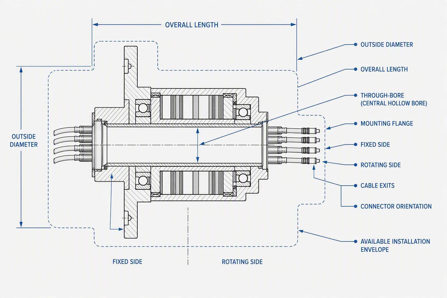
Mechanical fit is as important as electrical compatibility. Engineers should provide the available installation envelope, outside diameter, length restrictions, bore requirement, mounting interface, shaft arrangement, cable exit direction, connector orientation, and surrounding machine geometry so the supplier can evaluate physical integration before the design is finalized.
Installation Envelope and Dimensions
Give the space the slip ring must occupy.
Maximum outside diameter and maximum allowable length.
Through-bore diameter when a hollow center is needed.
Shaft dimensions where the unit mounts on or around a shaft.
Available clearance and any weight constraints.
Mounting and Mechanical Interface
State how the fixed and rotating parts are held.
Flange, shaft, or housing mounting.
Fixed and rotating side definition and which end turns.
Mounting-hole pattern, interface drawings, and alignment with surrounding structure.
A dimension with no mounting context can still be insufficient. The same diameter can be mounted several ways, and the supplier needs to know which interface your machine provides.
Cable and Connector Arrangement
Cables are part of integration, so define how they exit.
Lead length and cable exit direction: radial, axial, or angled.
Connector type and orientation relative to the machine.
Bend-radius limits and fixed-side versus rotating-side routing.
Torque, Vibration, and Mechanical Duty
Record the mechanical load on the unit.
Allowable rotational drag where it matters to the drive.
External shaft loading the unit must support.
Vibration and shock environment.
Balancing requirements for high-speed applications.
5. What Environmental and Protection Requirements Should Be Specified?
Environmental requirements should describe the real operating conditions around the slip ring. OEM engineers should provide temperature range, moisture, dust, water, chemicals, corrosion, vibration, outdoor exposure, and any hazardous-area need, because these conditions influence materials, sealing, enclosure design, cable interfaces, and the validation steps required.
Temperature and Operating Environment
Describe the true thermal surroundings.
Minimum and maximum operating temperature required by the project.
Indoor or outdoor installation.
Humidity, condensation risk, and nearby heat sources.
Dust, Water, and Ingress Protection
Explain the exposure that drives sealing, not just the IP number.
Actual dust exposure and how aggressive it is.
Water exposure: splash, spray, jets, washdown, or submersion.
Required IP rating when the project specifies one.
An IP rating is shorthand for a test condition, not a substitute for knowing whether the unit is hosed with hot water daily or simply sheltered indoors.
Chemicals, Corrosion, and Marine Exposure
State which agents the unit must survive.
Salt spray and coastal or offshore exposure.
Oils, greases, hydraulic fluids, and cleaning agents.
Chemical atmosphere and marine or offshore severity.
Vibration and Shock Requirements
Record the dynamic environment.
Expected vibration and shock conditions.
Customer-required validation standards where applicable.
Machine-specific mounting that transmits vibration.
Hazardous-Area and Compliance Requirements
Hand over the compliance framework the project must meet.
Installation country or target market.
Hazardous-area classification where applicable.
Required certification or acceptance framework.
Material restrictions, RoHS, or other customer-defined compliance, and required documentation.
Treat certification as a customer input. Provide it so the supplier can evaluate the design against it rather than assume a default.
6. Which Requirements Usually Determine Whether a Standard or Custom Slip Ring Is Needed?
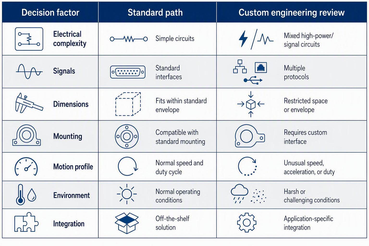
A standard slip ring may be suitable when the electrical circuits, signals, dimensions, mounting, speed, and environment match an existing configuration. A custom design becomes more likely when several requirements must be integrated simultaneously or when the machine has unusual electrical, communication, mechanical, or environmental constraints.
When a Standard Configuration May Be Sufficient
A standard unit is often the smoother, lower-risk path.
Common circuit arrangement with compatible current and voltage.
Standard signal interfaces.
Suitable dimensions, compatible mounting, and normal environmental needs.
When Customization May Be Required
Custom engineering earns its place when requirements move beyond the catalog.
Mixed power and multiple communication protocols in one unit.
Non-standard current distribution or a special through-bore.
Restricted installation envelope or a unique cable or connector arrangement.
High-speed or unusual motion profile, special environmental protection, or application-specific integration.
There is no automatic advantage to custom. A complete slip ring specification often shows that a standard configuration already fits, which can reduce cost and lead time.
Information That Helps a Supplier Evaluate Customization
Send the raw inputs for review.
Mechanical drawings, electrical schematic, and a circuit list with voltage and current per circuit.
Signal protocol information, installation constraints, and environmental requirements.
Project quantity and prototype-versus-production expectations.
7. What Drawings and Technical Files Should Be Included in the RFQ Package?
Drawings and technical files reduce ambiguity that cannot always be resolved through written specifications. OEM engineers should include machine-interface drawings, dimensional limits, electrical circuit tables, wiring information, connector requirements, motion profiles, and relevant acceptance criteria, because these files let a supplier confirm fit and interface rather than assume them.
Mechanical Drawings
Pictures of the space beat a paragraph of numbers.
Installation drawing of the available envelope.
Shaft or bore dimensions, mounting-hole pattern, and surrounding components.
Cable-routing restrictions.
Electrical and Wiring Information
Turn the electrical spec into a clear table.
Circuit table with voltage and current per circuit and a pinout.
Grounding and shielding requirements and connector information.
Signal Documentation
Document each data path.
Communication protocol, network or signal requirements, and channel quantity.
Cable type and shielding, with an interface diagram where useful.
Application References
Useful context often already exists.
Existing unit information for retrofit projects.
Photographs that clarify installation, previous drawings, machine schematic, and customer specifications.
Drawings matter most when space is constrained, when retrofitting or replacing, or when mounting, routing, or connector orientation is unusual.
8. What Testing and Acceptance Requirements Should Be Defined Before Ordering?
OEM engineers should state any project-specific acceptance requirements before quotation and design approval. Electrical safety checks, insulation requirements, temperature-rise evaluation, signal-integrity checks, mechanical verification, environmental testing, or customer inspection requirements should be discussed early rather than introduced after the design is complete.
Electrical Acceptance Requirements
Define how the unit is verified electrically.
Continuity, insulation, and grounding checks.
Dielectric or hipot requirements where specified and any customer-defined criteria.
Signal Performance Verification
Capture the data-side checks you expect.
Communication functionality, signal integrity, and network performance where required.
Noise or interference evaluation and acceptance limits.
Mechanical and Environmental Validation
Agree how fit and environment are proven.
Dimensional inspection and rotational performance.
Vibration, shock, or environmental testing when required.
Customer inspection or witness requirements.
Documentation Requirements
State the records you need delivered.
Inspection records, test reports, and compliance documents.
Drawings, pinout documentation, and product traceability when required.
Raising a new test after design approval can force rework. Put acceptance expectations in the RFQ so the supplier prices and plans for them.
9. What Commercial and Project Information Should Be Included Before Requesting a Quote?
Technical specifications alone do not define the full RFQ. OEM engineers should also provide quantity, project stage, prototype needs, expected production volume, schedule, documentation scope, spare-unit strategy, and service expectations, because these commercial inputs can influence the proposed configuration and the commercial response.
Project Stage
Tell the supplier where the project sits.
Concept, prototype, validation, pilot, or series production.
Retrofit or replacement of an existing unit.
Quantity Information
Volume changes how the offer is framed.
Prototype quantity, initial order quantity, and estimated production quantity.
Expected future demand when relevant.
Schedule Requirements
Timing shapes the whole plan.
Target prototype date, machine build schedule, production schedule, and requested delivery timing.
An RFQ is a request for a quotation, not a promise of lead time. State your target dates and let the supplier respond with what is achievable rather than assuming a fixed lead time in advance.
Spare Parts and Service Expectations
Include the after-sale picture.
Spare units, replacement planning, and maintenance expectations.
Field-service and documentation expectations where relevant.
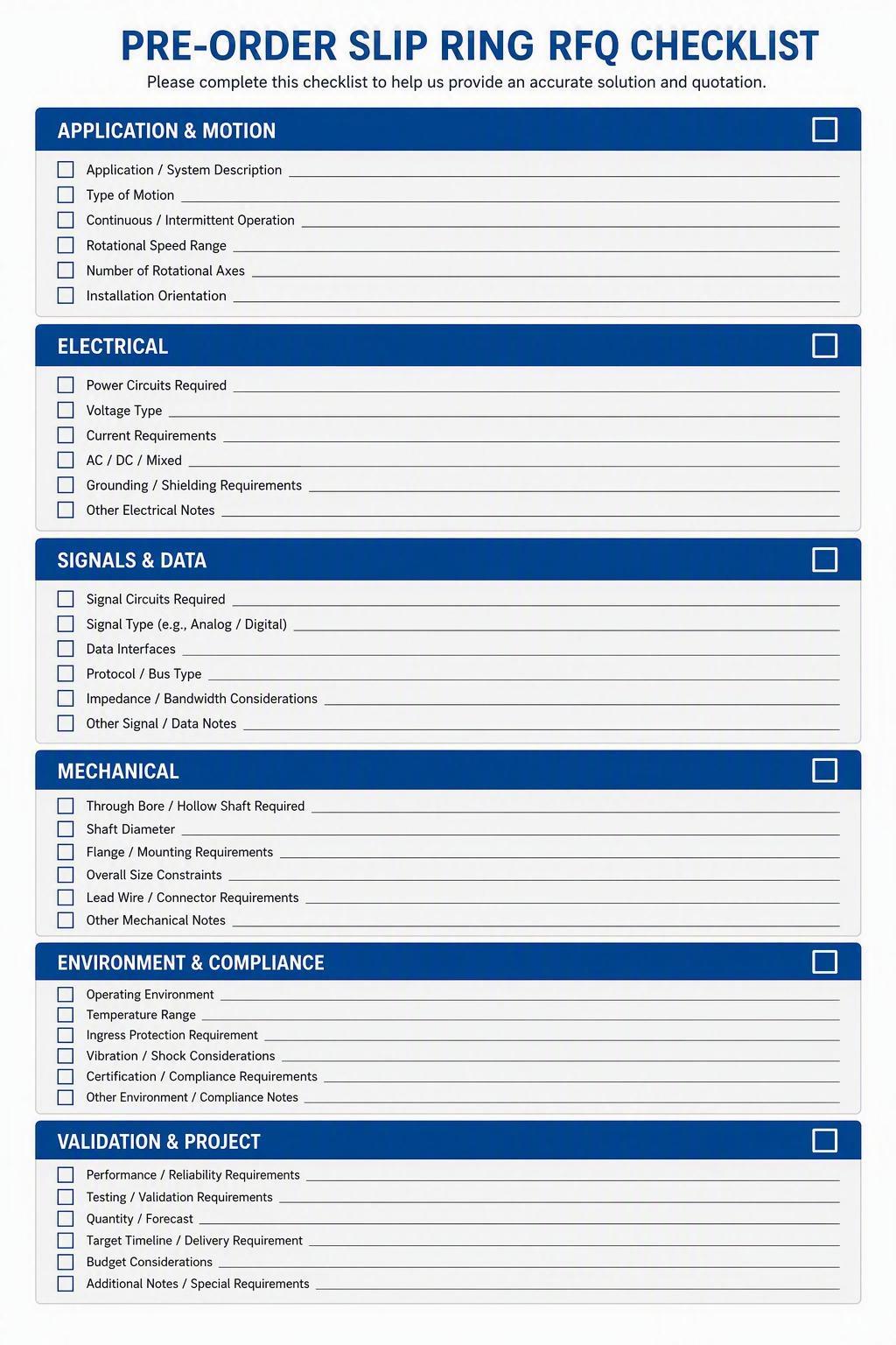
10. Complete Slip Ring RFQ Checklist
A complete slip ring RFQ should let the supplier understand the application without repeatedly requesting basic information. Use the following checklist to confirm that the electrical, signal, mechanical, environmental, validation, and commercial requirements have been prepared before you send it.
Application and Motion Checklist
Machine application defined
Rotation type defined
Operating speed defined
Duty cycle defined
Start-stop pattern defined
Reliability or service expectations defined where relevant
Electrical Checklist
Circuit count defined
Voltage defined by circuit or circuit group
Continuous current defined
Peak or inrush current defined where relevant
AC or DC operation defined
Grounding and isolation requirements defined
Signal and Data Checklist
Signal types identified
Protocols identified
Channel counts identified
Required communication performance defined
Shielding requirements defined
Connector or cable interfaces defined
Mechanical Checklist
Maximum outside diameter defined
Maximum length defined
Through-bore or shaft requirement defined
Mounting method defined
Cable exit direction defined
Connector orientation defined
Mechanical drawing attached where available
Environmental and Compliance Checklist
Operating temperature requirement defined
Dust and water exposure defined
Corrosion or chemical exposure defined
Vibration or shock conditions defined
IP requirement defined where applicable
Compliance or certification requirements defined where applicable
Validation and Project Checklist
Required testing identified
Required documentation identified
Prototype quantity identified
Production quantity identified
Project schedule provided
RFQ scope clearly stated
11. What Information Is Most Commonly Missing From Slip Ring Specifications?
Incomplete specifications often contain broad labels without the operating details needed for engineering review. Common examples include total current without current per circuit, "Ethernet" without protocol requirements, speed without duty cycle, dimensions without mounting information, and an IP rating without describing the real environment.
Giving Only Total Current Instead of Current Per Circuit
A single total hides how load is distributed. If circuits run at different levels, only per-circuit current lets the supplier size each ring and check thermal loading. Provide voltage and current per circuit instead of a grand total.
Specifying Maximum Speed Without the Actual Duty Cycle
Maximum RPM without duty cycle leaves real demand unknown. A high speed for seconds is not sustained operation. State the normal speed, the maximum, how long each runs, and how often the unit cycles.
Writing "Ethernet" or "Data" Without the Required Interface Details
"Data" does not identify a protocol, and "Ethernet" does not tell the supplier the rate or channel count. Name the protocol, channel count, required performance, shielding, and connector interface.
Providing Dimensions Without the Mounting Interface
A diameter and length say little about how the unit is held. Add the mounting type, fixed and rotating sides, and hole pattern so fit is confirmed rather than assumed.
Requesting an IP Rating Without Describing the Environment
An IP number is shorthand for a dust or water test. Unless the real conditions — temperature, washdown, chemicals, salt — are described, the rating may not match actual exposure.
Omitting Peak or Inrush Loads
Continuous current alone does not cover motor starts or transients. Provide the peak or inrush current, its duration, and frequency so the design handles steady and transient demand.
Omitting Cable and Connector Requirements
The slip ring does not end at its housing. State lead length, exit direction, connector type and orientation, and bend-radius limits so wiring is not left to guesswork.
Sending an RFQ Without Drawings for a Space-Constrained Installation
When the envelope is tight, numbers rarely tell the whole story. Include a mechanical drawing of the available space, the bore, and surrounding structure.
Introducing Testing or Documentation Requirements After Design Approval
A test added late can change the design and cost. Put validation and documentation expectations in the RFQ so they are priced and planned from the start.
12. How Can JINPAT Support the Slip Ring Specification Process?
JINPAT is best used as the next engineering contact after you have collected the main application requirements. The company reviews customer-provided specifications, discusses standard versus custom requirements, and moves from application data toward a product recommendation or quotation using its documented rotary-transmission and custom-engineering capability.
Application Requirement Review
Submit your electrical, signal, mechanical, motion, and environmental information together with any drawings. A complete package lets an engineer match your machine to the right configuration. JINPAT's documented engineering focus covers power, signal, and data transmission across heavy machinery and industrial rotating systems, including cranes and lifting equipment where continuous rotation and harsh outdoor conditions are common.
Standard or Custom Configuration Discussion
Your supplied specification is used to decide whether an existing configuration may fit or whether application-specific engineering should be discussed. The decision stays grounded in your actual circuits, signals, dimensions, movement, and environment.
Next-Step Options
Submit your slip ring specification for an application review.
Send your mechanical drawing and electrical requirements.
Request a product recommendation based on your operating conditions.
Request a quotation for a defined standard or custom configuration.
You can reach the engineering team through the JINPAT site or read the latest JINPAT news for related engineering guidance while you assemble your package.
13. Frequently Asked Questions About Slip Ring Specifications
What Information Is Essential for a Slip Ring RFQ?
The essential minimum covers the machine application, circuit count with voltage and current per circuit, peak or inrush conditions, signal types and protocols, rotational speed and duty cycle, mounting and envelope dimensions, the actual operating environment, and target quantity and schedule. That detail lets a supplier review the application without asking you to repeat the basics.
Do I Need a Drawing Before Requesting a Slip Ring Quote?
A drawing is especially useful for custom mounting, limited installation space, retrofits, special through-bores, or unusual cable routing. If your fit is constrained or your interface is non-standard, a mechanical drawing removes ambiguity faster than a written dimension list.
Should I Specify Both Continuous and Peak Current?
Yes, when both occur in your application. Continuous current drives steady-state thermal design, while peak or inrush current checks transient margins. Providing only one of the two can lead either to an undersized design or an unnecessarily conservative one.
What Should I Specify for Ethernet, CAN, or Encoder Signals?
Provide the exact protocol, the channel quantity, the required performance or data rate, the shielding, and the connector and cable interface. A generic label such as "Ethernet" or "encoder" is not enough, because different standards place different demands on the rotating path.
How Do I Know Whether I Need a Standard or Custom Slip Ring?
The decision depends on how closely your electrical, signal, mechanical, motion, and environmental requirements match an existing configuration. If most requirements fit a standard offer, standard is usually faster and lower cost; custom becomes relevant when several needs must be integrated or the machine has unusual constraints.
Should Testing Requirements Be Included Before Ordering?
Yes. Project-specific validation and documentation expectations should be communicated before design approval or quotation whenever possible. Tests introduced late can change the design and the cost, so stating them early gives the supplier a complete picture.
Can I Send an Existing Slip Ring Model Number for a Replacement Project?
An existing model number is a useful starting reference, but the supplier should still receive the actual machine requirements, dimensions, wiring, and operating conditions. The number alone may not reflect every current need, so pair it with the full specification to confirm compatibility.
Conclusion: Turn Your Application Requirements Into a Complete Slip Ring RFQ
Define the machine application and motion profile, specify electrical circuits and signals, provide mechanical and environmental requirements, identify validation and documentation needs, attach drawings where useful, add quantity and schedule information, and submit the complete package for engineering review. A complete slip ring specification reduces ambiguity and helps both the OEM and the supplier evaluate the application efficiently.
The work you do before sending an RFQ determines how quickly an engineer can respond and how accurate the quotation will be. Every circuit, protocol, dimension, environment, and schedule detail you include removes a guess the supplier would otherwise have to make.
If you have gathered your slip ring specification and drawings, the practical next step is to submit them to JINPAT for an engineering application review, or to request a product recommendation or quotation based on your electrical, signal, mechanical, environmental, and project requirements. A complete package is the fastest route from "I need a slip ring" to a clear engineering response.